Joint Research Centre, Building 75N – INSEL – Ispra (Italy)

Joint Research Centre, Building 75N INSEL - Ispra (Italy)

ClientEuropean Commission

Work activitiesDetailed design

PlaceISPRA (ITALY)

SURFACE1000sqm

Period2017 - 2018

Overview

The project involves the construction of a building within the European research centre (JRC) located in the municipality of Ispra where Unit 08 will be located, which deals with studies and standardization of INSEL nuclear safety and security measures (Ispra Nuclear Safeguards, Security & Standardization Laboratory).

The basic design solution was to define two macro-areas within the building so that the administrative activities (i.e. offices, meeting rooms and accessory services) could be grouped together in an area of 650 m² arranged on two levels, separating them from laboratory and research activities with an area of 1000 m².

Similar Projects

Joint Research Centre, “Multi-purpose” sport hall Building 10P, Ispra (Italy)

Joint Research Centre, "Multi-purpose" sport hall Building 10P, Ispra (Italy)

ClientEuropean Commission

Work activitiesDetailed design, Supervision of works

PlaceISPRA (ITALY)

SURFACE1100sqm

Period2017 - 2018

Overview

The project involves the construction of a sports building on the perimeter of the European research centre (JRC) located in the municipality of Ispra. The goal of the project is to replace, by dismantling and demolition, one of the current marquees with a permanent multi-purpose gymnasium, with characteristics that allows it to be also used for collective events such as ceremonies, school parties, etc. This large number of sports disciplines required a dimensioning of the minimum sports area size of 38 by 22m. To meet these requirements, the new building has a larger surface area than the current one, as the project provides for the expansion of the floor area in the direction of the hill on the southern slope towards the Club House in order to make several playgrounds available at the same time. The resulting building has a size of about 41m by 30m and a maximum height of 11m.

Similar Projects

Milan Metro Line 4 (Italy)

Milan metro line 4 (Italy)

NEW PUBLIC TRANSPORT IN MILAN

ClientSalini Impregilo S.p.A. – Astaldi S.p.A.

Work activitiesPreliminary and Detailed design

lenght15 km

PlaceMILAN (ITALY)

Period2012 - ongoing

Overview

The Line 4 is a new underground line under construction in Milan, part of the city metro system and it will be the second driverless line in the city of Milan The line will be 15 km long with 21 stations.

Alpina is in charge of designing preliminary and detailed design of the structural and geotechnical works for 8 underground stations, 3 inter-stretch building structures, 3 tunnels, 1 bridge and n the design assistance on site during construction.

The works were engineered in loose soils below the water table, alongside the existing buildings or infrastructures in the city centre. The underground main structures are built using bottom-up procedures below water table or using combined bottom-up and top down techniques for high excavation depths (up to 30 m, 20 m below the water table).

Similar Projects

Milan Metro Line 5 (Italy)

Milan Metro Line 5 (Italy)

NEW PUBLIC TRANSPORT IN MILAN

ClientAstaldi S.p.A.

Work activitiesPreliminary, Final and Detailed Design

PlaceMILAN (ITALY)

Period2000 - 2015

Overview

Alpina carried out the final design of the structural and geotechnical works of five stations of the Milan Metro Line 5, as well as the tunnels of the Garibaldi junction. In particular engineering designs were provided for the Isola, Garibaldi, Monumentale, Cenisio and Tre Torri stations, all of the underground works of the Isola and Monumental stations for a total of about 1,8 km of tunnels in the urban area, in loose soil below the water table, alongside buildings or existing infrastructures such as the 70 m high tower at the AC Hotel.

Similar Projects

Railway line Turin Lyon – D’Avrieux ventilation shaft – (France)

Railway line Turin Lyon – D’Avrieux ventilation shaft – (France)

ClientTELT - Tunnel Euralpin Lyon Turin

Work activitiesMaitre d'Oeuvre (MOE): Final Design (PRO), Preparation of Tender Documents (DCE), Review of Detailed Design (EXE) and Work Supervision

PlaceITALY & FRANCE

Depht500 m

Period2016 - 2017

Overview

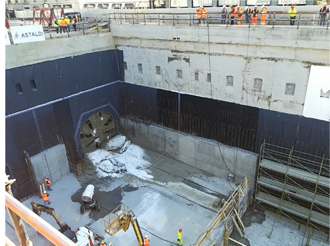
As part of the project for the new Lyon – Turin high speed railway, this contract concerns the construction of the Avrieux shafts, a part of the safety site, a section of the base tunnel towards La Praz and the tunneling machinery chambers of the future section 05.

The main works concerning the shafts are broken down into two parts:

  • Part 1 – Avrieux Shafts (n. 4 ventilation shafts);
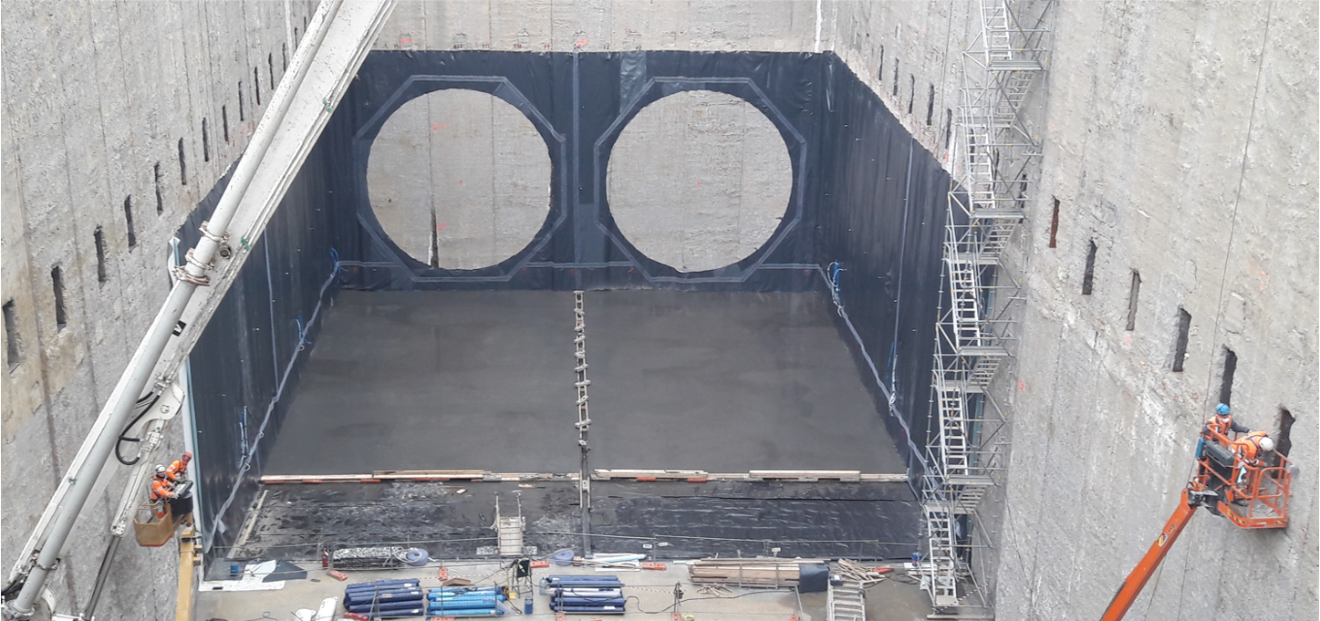
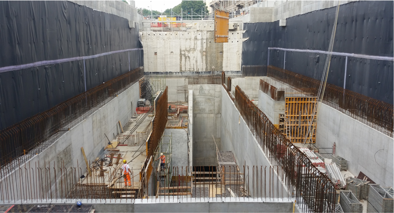
  • Part 2 – Tunnels at the bottom of shafts (connecting gallery, room at the bottom, ventilation tunnel, heads of the smoke shafts, smoke shaft at the intertube gallery). The basic solution involves the construction of four shafts of 4,26 m internal diameter and 5,20 m excavation diameter dug at Raise Boring aligned in pairs on two rows spaced by 2 diameters.
  • The 4 shafts have a depth of about 500 m each, from the platform of Avrieux to reach the room at the bottom of the wells.
  • The room at the bottom of the shaft is connected to the ventilation tunnel.
  • The inter-distance of the shafts is 12,5 m with the exception of the two shafts at the entrance of the ventilation tunnel, which are arranged at 20 m distance to ensure the maneuvering area of the machines.
  • The installation of the shafts must be compatible with the size of the opening of the ventilation plant at surface in order to directly open the 4 shafts in the future central platform. The constraint to be met includes the requirement to enclose the shafts in a rectangular area with footprint 28,0 mx 18,39 m.
  • The excavation section of each of the four shafts is 21,24 m².

The construction method chosen consists of 4 main phases which are as follows:

  1. Dig a pilot hole from top to bottom in about 15 inches (RVDS directional drilling).
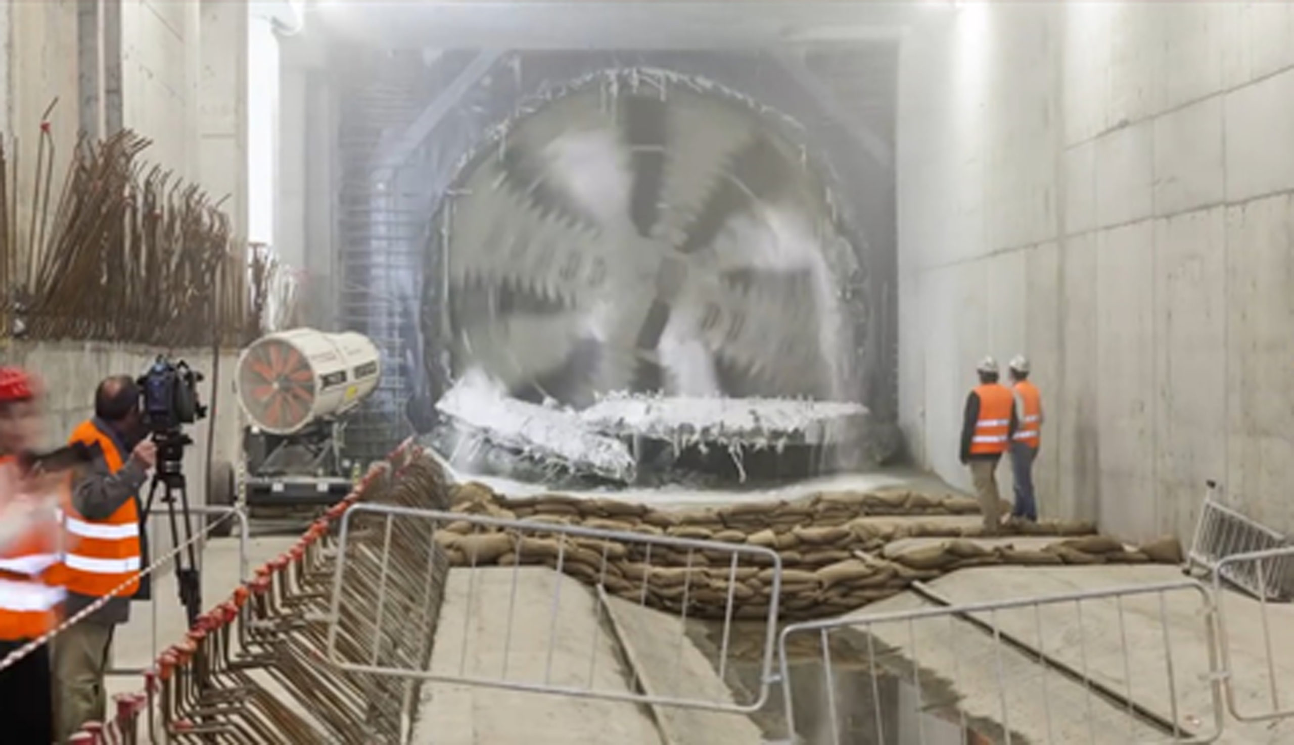
  2. Bore up to 5,20 m in diameter with the Raise-Boring method.
  3. Install a temporary support from top to bottom once the bore is finished.
  4. Final coating of the shaft from the bottom to the top with slippery or creeping formwork.

A jet-grouting soil consolidation treatment is necessary before RBM digging to ensure shafts wall stability.

The cuttings produced by boreholes fall at the base of the shaft in each sector of the basic chamber, divided into independent sectors by temporary partitions.

The construction of the concrete final lining is done by sliding or creeping formwork, from the bottom to the top. The presence of a seal between the coating and the solid structure significantly reduces the transmission of the weight of the coating to the rocks by friction. For this reason, in order to provide support to the coating, which would otherwise be suspended to the top of the shaft, 12 precast concrete hemispherical supports every 10m are anchored to the solid structure by HA32 bolts, 2 m long, inclined by 20°. The execution of the shafts is done in a soundproof acoustic shed able to limit the noise nuisances within the limits set in the NRE.

Similar Projects

Railway line Turin – Lyon, access tunnel of Saint Martin la Porte (France)

Railway line Turin – Lyon, access tunnel of Saint Martin la Porte (France)

ClientTELT - Tunnel Euralpin Lyon Turin

Work activitiesMaitre d'Oeuvre (MOE): Final Design (PRO), Preparation of Tender Documents (DCE), Review of Detailed Design (EXE) and Work Supervision

PlaceITALY & FRANCE

Lenght57 Km

Period2003 - ongoing

Overview

The Lyon–Turin Base Tunnel is a key element of the trans-European Network for passengers and freight, the West-Eastlink of Corridor V, connecting Lisbon to Kiev.

The twin tube 57 km Base Tunnel will be excavated through 4 access tunnels. Three different access adits are conceived on the French side: Saint-Martin La Porte, La Praz and Modane, and one on the Italian side: La Maddalena.

The excavation of the base tunnel has started with the 8 km section from Saint-Martin La Porte to La Praz.

Alpina carried out the Supervision of works of the access tunnel in Saint-Martin La Porte (in JV with Egis and Antea) and currently is carrying out the Supervision of works of the first 8 km section of the base tunnel (in JV with Egis).

Similar Projects

Angat Water Transmission and Improvement project – AWTIP (Philippines)

Angat water transmission and improvement project, AWTIP – (Philippines)

ClientCMC Ravenna

Work activitiesPreliminary and Detailed design

PlaceANGAT RIVER (PHILIPPINES)

Surface length 1015 m

Period2015 - 2018

Overview

Angat river water is convoyed from IPO dam to Bigte through the three existing tunnels, out of which only Tunnel n.°1 is today operational. The Angat Water Transmission Improvement Project (AWTIP, the “Project”) aims to improve the reliability and security of the raw water transmission system through partial rehabilitation of the transmission system from IPO to La Mesa and the introduction of water safety, risk and asset management plans. The Project includes the following works:

  • a new intake structure at Ipo reservoir
  • a new tunnel n.°4 (6,4 kilometers long with an internal diameter of 4,2 m excavated for its entire length with a Tunnel Boring Machine), which connects Ipo reservoir to Bigte basin n.°3 and conveys a minimum flow rate of 19 mᶟ/S.
  • a transition basin at outlet of new tunnel n.°4
  • an open channel
  • modification of basin n.°3
  • an access roads system

Similar Projects

Itare dam water supply project (Kenya)

Itare dam water supply project (Kenya)

ClientCMC Ravenna

Work activitiesFinal design, detailed design and assistance during construction

PlaceNAKURU (KENYA)

Period2016 - 2018

Overview

This project is aimed at improving water supply in the Nakuru Municipality and its environs: Molo, Elburgon, Salgaa and Njoro towns.

Integrated water system for the supply of the potable water from the new Itare Dam to the villages of Nakuru is mainly composed by:

  • a dam (total storage volume of 11,6 Mm³);
  • a raw water pipeline of 1,25 km long and 1200 mm diameter;
  • a WTP consisting of sedimentation units, filters, chlorination;
  • a treated water pipeline, 63 km long and 1200 mm diameter;
  • a free surface water transfer tunnel 3,2 m diameter and 14 km long;
  • a treated water pipeline, 33 km long and 1200/900 mm diameter;
  • a 5000 m³ reservoir at Ngata site;
  • a distribution pipeline 32 km long.

Similar Projects

High speed and capacity railway Brescia-Verona (italy)

High speed and capacity railway Brescia-Verona (Italy)

ClientCepav 2

Work activitiesDetailed design

PlaceBRESCIA- > VERONA (ITALY)

Period2018 - Ongoing

Overview

Alpina took part in the design of a significant section of about 15 km and related structural works.

In particular, Alpina developed the design of the following parts of the project:

  • Embankments, open cuts, and U-shape structural walls between ch. 122+250 and ch. 140+180;
  • Cut and cover tunnel “Madonna del Frassino” including entrance works;
  • Cut and cover tunnel “Santa Cristina” including entrance works;
  • Tunnel “Colle Baccotto” including entrance works;
  • Cut and cover tunnel “Mano di Ferro” including entrance works;
  • Road underpass “via Mantonava”.

In particular, the Tunnel “Colle Baccotto” is designed in clay, silt and sand layers, for long section under water table level, with important issues related to the settlement and the stability of the embankments of the adjacent highway Milan-Verona and of the flyovers.

Similar Projects